Preparing for the CCNP TSHOOT exam
Published on 2017-09-03This week I finally finished my CCNP R&S; studies by passing the TSHOOT exam. This exam was the most fun to prepare because it brings all the previous efforts together and because it’s hands-on. I’d like to share my preparation strategy and my lab build hoping that it will help other people too.
The TSHOOT exam consists of tickets and multiple choice questions. I won’t comment on the exact content of the exam of course, but it’s general knowledge that Cisco provides the network topology of the exam to the public. It can be found here. You can also get familiar with the exam simulator over here.
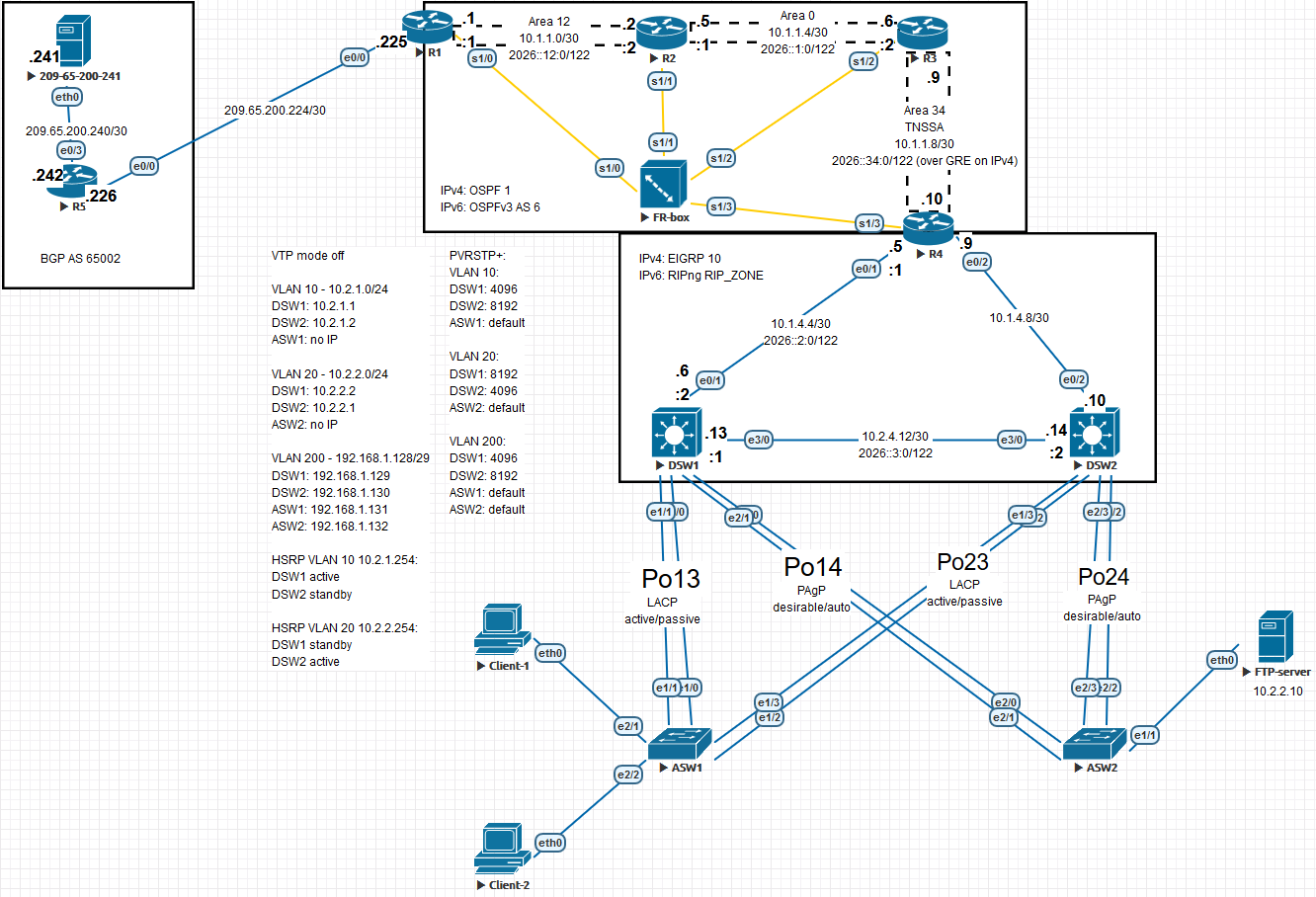
Although you can view the network topology before taking the exam, there is still a lot left open. The network can be built with different configuration choices being made for a lot of the technologies used. Some technologies might be present, or they might not be. I’ve built the network in Eve-NG, like this (click the picture or this link for a readable version):
As you can see, I like to add a lot of visual information to the networks I build in Eve-NG to make everything as clear as possible. It’s a bit tedious to set it up like this but it helps with focus and troubleshooting. There are a lot of things to pay attention to when building this network, so I will provide the following list of things to consider:
- The port channels can have different protocols and negotiation settings. I mixed it up a bit to keep all the different configs memorized
- Speaking on the topic of port channels: the link between the two distribution switches is supposed to be a routed port. I ran into trouble getting this to work so I cut it back to a single link. A colleague pointed out that he got this to work by first setting the underlying interfaces to routed ports using the
no switchportcommand - The TSHOOT lab demo I linked contains some config that you can view. I used it as inspiration but it isn’t a lot because the network in the demo setup is very watered down
- If you look closely at the topology Cisco provided you can see that R4 is the DHCP server. That means you need IP helpers on the VLAN interfaces of the distribution switches. If you want to go all out you can incorporate DHCP snooping too
- I found the Cisco topology a bit unclear regarding the connection from R1 to the cloud. You can see that I used a simple BGP connection to an extra router that connects to a “web server” (you can only ping it) with the sole purpose to have a network to try and reach out of the internal network
- Routers R1 - R4 seem to be chained using a point-to-point frame relay construction. There are a couple of different choices you can make here. I used subinterfaces on all 4 routers to make life “easy”. You can opt out of subinterfaces on R1 and R4 because only a single network is connected to each of their serial links. In that case you have to use frame relay maps. You can also configure the links as point-to-multipoint. All of this stuff influences the behaviour of your OSPF neighborships so watch out for that. I used this article to brush up on some frame relay details
- R1 provides NAT with PAT
- The distribution switches use HSRP as a gateway for VLAN 10 according to the Cisco topology. I set it up for VLAN 20 as well because it just feels wrong otherwise
- The access switches have management reachability from the distribution switches via VLAN 200
- This is personal preference but I thought I’d comment on the order in which I built this lab. I started by placing each device from the entire topology, then added all the links. After that I start doing the configs. In my case I started with the edge, then did all the internal routers. I try to have local layer 3 reachability first and then configure all the routing protocols. In this case it is quite a lot of config just for the reachability because of all the frame relay stuff
- You can choose to use VTP for VLAN distribution. I hate VTP so I didn’t use it anywhere
- I made VLAN’s 10 and 20 passive interfaces for the EIGRP processes on the distribution switches, to make sure the switches don’t form neighborships over those VLAN’s
- I had some trouble wrapping my head around the IPv6 over GRE tunnel between R3 and R4. There are two posts on the awesome INE blog that helped out
- If you look at the IPv6 topology Cisco provided the IPv4 addresses between R3 and R4 are incorrect. They are correct on the IPv4 topology however so you should configure those
- There are a couple of technologies that I did not include but that might be used in this network. Think about ACL’s, VACL’s, NAT64 at the edge and authentication of routing protocols. If you don’t have those technologies fresh in mind it might be a good idea to configure them
As a nice convenience I have added all the running configs for my lab devices, to be found here. Thank you for reading a Conproly article. Please feel free to reach out on social media if you have any questions of comments.


